Swept Flange.
In SolidWorks, the Swept Flange feature is used in sheet metal design to create a flange that follows a specified path or contour. It allows you to sweep a selected profile along a path to create a sheet metal flange with a custom shape. The Swept Flange feature provides flexibility in designing complex sheet metal parts with curved or non-linear flanges.
The advantages of using the Swept Flange feature in SolidWorks for sheet metal design include:
- Design Flexibility: Swept Flange offers greater design flexibility by allowing you to create sheet metal flanges with complex and non-linear shapes. It enables you to design parts with unique contours and profiles that meet specific functional or aesthetic req.
- Smooth Transitions: The Swept Flange feature ensures smooth and continuous transitions between different sections of the flange. It allows for seamless connections between straight segments, curves, or combinations of both, resulting in aesthetically pleasing designs.
- Customizable Bend Profiles: The Swept Flange feature provides the ability to define custom bend profiles along the swept path. This allows for variations in bend radius, twist, or taper along the length of the flange, providing greater control over the part's geometry.
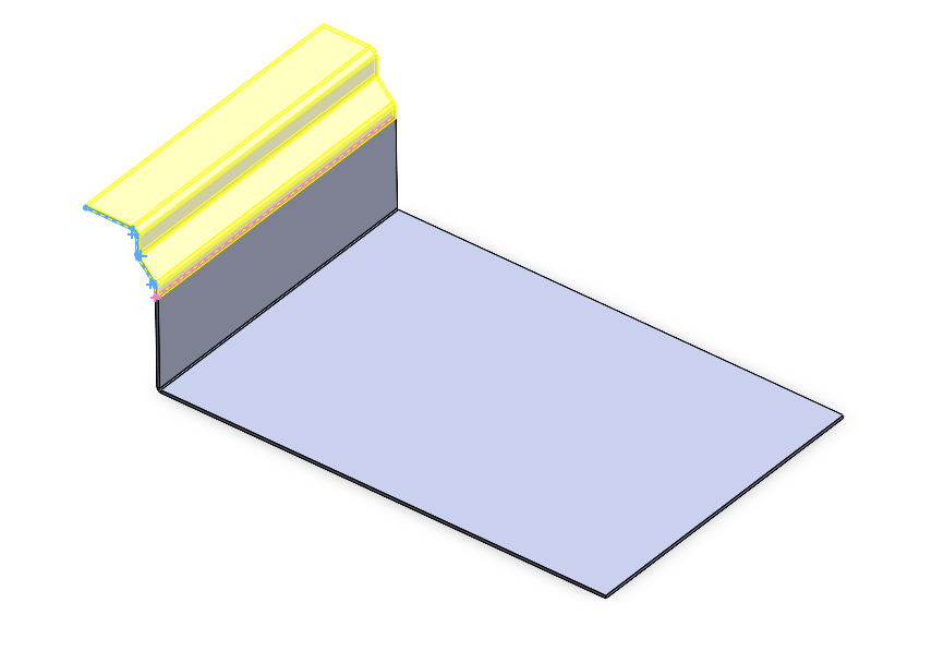
Steps for Swept Flange.
- Select Swept Flange.
- Select Plane for Draw Path Sketch.
- Draw Sketch and Exit
- Select Edge in Properties Manager
- Click ✅
Overall, the Swept Flange feature in SolidWorks empowers designers to create sheet metal parts with custom-shaped flanges that follow specific paths or contours. It offers design flexibility, efficient modeling, smooth transitions, customizable profiles, and improved part strength, making it a valuable tool for sheet metal design applications.